Froyo Android.
The block diagram below describes the connections between the sensor and the Android system.
After having the above schematic ready, it is time for the new kernel-bootloader-rootfs system compilation which will include the DALLAS DS1621 driver which already exists in the kernel. You just have to include it in your compilation.
Before start the compilation you have to add some code in the
"board-omap3tao3530.c" which exists in the folder:
"../rowboat-android/kernel/arch/arm/mach-omap2".
In this file find the :
static struct i2c_board_info __initdata tao3530_i2c_3_boardinfo[]={
};and add inside it the following lines:
#if defined (CONFIG_SENSORS_DS1621)
{
I2C_BOARD_INFO("ds1621",0x49),
.type = "ds1621",
},
#else
{},
#endif
After that find the line:
omap_register_i2c_bus(3,100,tao3530_i2c_3_boardinfo,ARRAY_SIZE(tao3530_i2c_3_boardinfo));
and make sure that is like this.
For this project I use the source from the Rowboat Project.
When you are in the menuconfig of the Kernel you have to go:
"Device Drivers->Hardware Monitor->Dallas DS16212" (enable the driver and the hwmonitoring debugging messages).
After completing successfully the building of the system you have to boot the Thunder Board with your new compilation, which includes now the driver for the DS1621. To boot from the SD card you have to stop stop the auto-booting from the NAND memory, by pressing a button and then insert:
>setenv hh_android_args 'setenv bootargs mem=${mem_size} androidboot.console=ttyS2 console=tty0 console=${console} ${video_mode} ${extra_options} ${network_setting} root=${mmcroot} rootfstype=${mmcrootfstype} init=/init'
>setenv bootcmd 'mmc init; fatload mmc 0 84000000 uImage; run hh_android_args; bootm 84000000'
>boot
At the same time you can browse the folder of the Android SDK in order to use the ADB (Android Debug Brigde) through a USB connection.
Usually is very helpfull to load the busybox in the new Andoid/Linux system.
So, after detecting the Android device from the ADB, using the following command
>./adb devices
you can "push" the busybox in the android device:
>./adb push /home/kostas777711/busybox /data/busybox
if for example the busybox folder is in this location: /home/kostas777711/busybox /data/busybox
Then:
>./adb shell , to enter the shell
>export PATH=/data/busybox:$PATH , to add it in the PATH of the system
>cd /data/busybox , browse its folder
>chmod 777 * , change the permissions of the whole folder of busybox
>busybox --install , install busybox
Then browse to:
>cd /sys/bus/i2c/devices/3-0049
>ls
withe ls you can see the attributes of the driver. By executing:
>cat temp1_input
you can read the temperature from the temperature register.
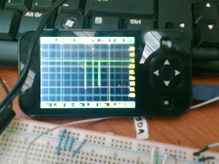
With an oscilloscope you can also "read" the SDA pin of the sensor.
In order to achieve this you can create an infinite loop in the Linux command line of the Android device (from the "adb shell"):
#while :
>do
>cat temp1_input
>done
With this you will be able to read the temperature in the "adb shell" and also notice the transmission of data from the oscilloscope.
At the same time that this project is running, I have set up another project mainly for testing using another DS1621 temperature sensor, the mbed NXP1768 PIC and a 4 lines LCD JHD204A. The NXP1768 communicates through an I2C bus with the sensor and parallel with the LCD. In this case, we have to add pull-up resistors in the SDA and the SCL lines.
Here are some pictures of the project:
 |
| Android Thunder Board connected with the DS1621 and the testing board (NXP1768, LCD JHD204A & DS1621) and the embedded oscilloscope connected to the SDA of the Thunder Board. |
 |
| The data of the SDA line. |
 |
| Display the temperature on the JHD204H LCD. |
 |
| Monitoring the output from the "adb shell" after the infinite loop. |
 |
| Thunder Base Board, Tao3530 and 4.3" touchscreen display. |
 |
| Closer look to the external connections. |


This is a great project!!! Nice Job Bro.
ReplyDeleteThanks for your nice words troy.
ReplyDeleteNice. I like it. I have a one question. I use MPU6050 3 axis sensor. Because Thunder board's kernel hasn't MPU6050's driver. How can i solve this problem.
ReplyDelete